
FutureSDR 2
This is the second post on FutureSDR, an experimental async SDR runtime, implemented in Rust. While the previous post gave a high-level overview of the core concepts, this and the following posts will be about more specific topics. Since I just finished integration of AXI DMA custom buffers for FPGA acceleration, we’ll discuss this.
...and custom buffers for FPGA acceleration (Xilinx AXI DMA). Both blocking and async mode :-) https://t.co/1vmxNMwiuv pic.twitter.com/tms5IzdhdX
— Bastian Bloessl (@bastibl) January 27, 2021
The goal of the post is threefold:
- Show that the custom buffers API, presented in the previous post, can easily be generalized to different types of accelerators.
- Show that FutureSDR can integrate the various interfaces and mechanisms to communicate between the FPGA and the CPU.
- Provide a complete walk-through of a minimal example that demonstrates how FPGAs can be integrated into SDR applications. (I didn’t find anything on the this topic and hope that this shows the big picture and helps to get started.)
The actual example is simple. We’ll use the FPGA to add 123 to an 32-bit integer. The data will be DMA’ed to the FPGA, which will stream the integers through the adder and copy the data back to CPU memory. It’s only slightly more interesting than a loopback example, but the actual FPGA implementation is, of course, not the point. There are drop-in replacements for FIR filters, FFTs, and similar DSP cores.
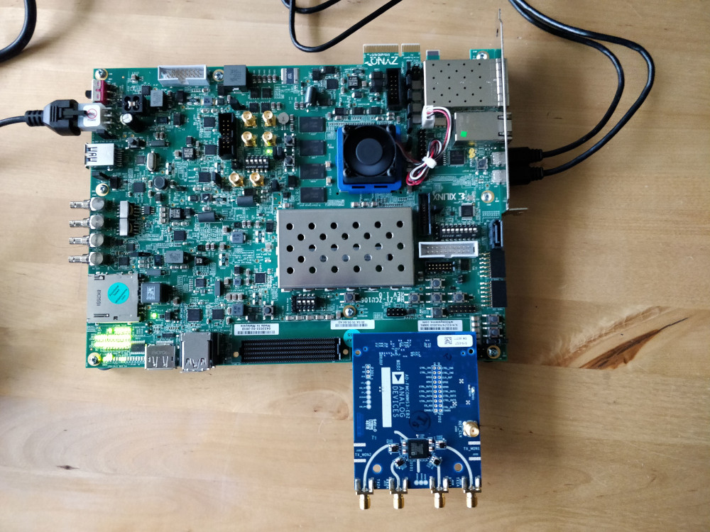
I only have a Xilinx ZCU106 board with a Zynq UltraScale+ MPSoC. But the example doesn’t use any fancy features and should work on any Zynq platform.
Vivado HLS
Since I don’t know any hardware description languages (HDLs, like Verilog or VHDL), I used Vivado HLS to create the adder block.
HLS allows to synthesize a subset of C/C++ and comes with helpful libraries for bus interfaces and FPGA-specific data types.
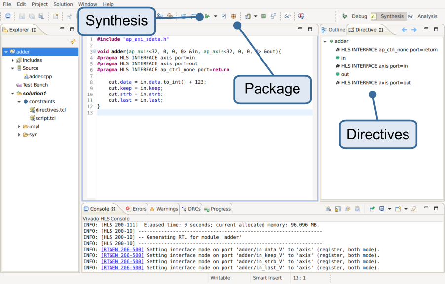
I created a new project that only configures the target board, added an adder.cpp source file, and implement a adder() function:
#include "ap_axi_sdata.h"

void adder(ap_axis<32, 0, 0, 0> &in, ap_axis<32, 0, 0, 0> &out){
#pragma HLS INTERFACE axis port=in
#pragma HLS INTERFACE axis port=out
#pragma HLS INTERFACE ap_ctrl_none port=return

    out.data = in.data.to_int() + 123;
    out.keep = in.keep;
    out.strb = in.strb;
    out.last = in.last;
}
Its input and output are AXI Streams of 32-bit integers ap_axis. ap_ stands for arbitrary precision integers.
(In contrast to the CPU, the FPGA is not tight to 8/16/32/64-bit integers, but can work with any bit-width.)
The axis extension, in turn, indicates and AXI stream.
AXI is a set of bus protocols that can be is used to connect IP blocks or other components on a chip.
In this case, we use the stream interface to process each integer one-by-one.
Since AXI is a standardized protocol, we can directly connect our adder to the DMA controller without having to reinvent the wheel.
While the interface type would, in this case, be clear from the function arguments, the interface has to be specified explicitly through directives.
This is done through the Directives tab on the right.
The directives can be stored as metadata of the project or added to the source.
As you can see, I opted for the latter.
The additional ap_ctrl_none directive disables optional ports that are mainly used for initialization, which is not needed in this case.
The example also forwards basic control signals of the AXI stream (keep, strb, and last).
My understanding is that these signals are, in this example, not strictly required (according to the AXI spec), but the AXI DMA block expects them to be present.
Before we can synthesize the adder, we have to specify the top-level function. Since we defined only one function, it would be obvious, but we, nevertheless, have to set it at Project -> Project Settings -> Synthesis -> Browse. To add the block to an FPGA design, we have to (1) synthesize and (2) package it for use in Vivado (see screenshot).
Vivado IP Integration
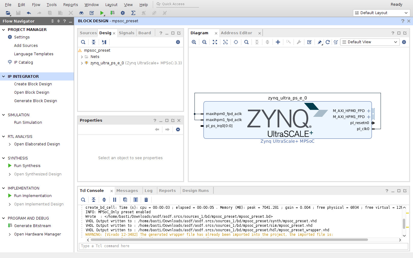
Having implemented the function that we want to accelerate, we are ready to create the FPGA design in Vivado. I created an empty example project for the board that just includes the processing system (PS, i.e., the ARM processor).
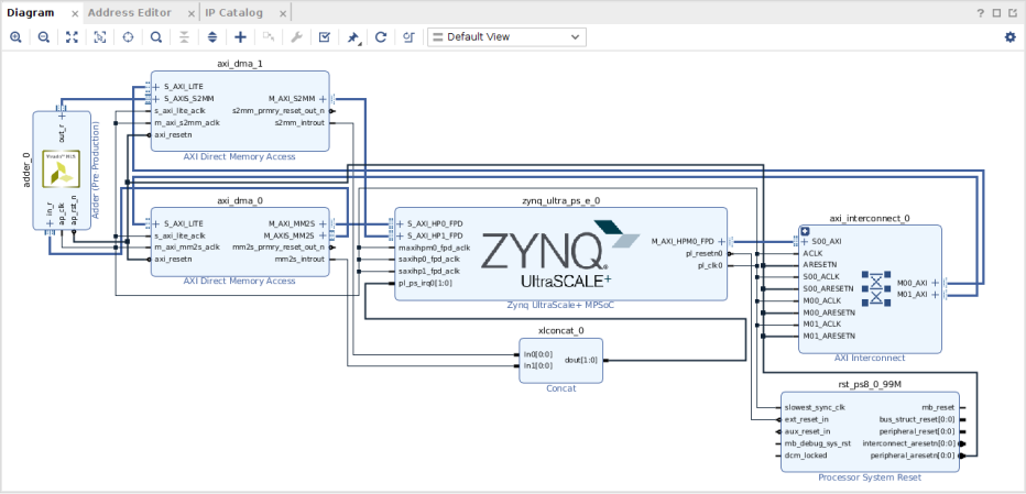
Based on this, we can implement a loopback example with two DMA blocks. It should look like this:
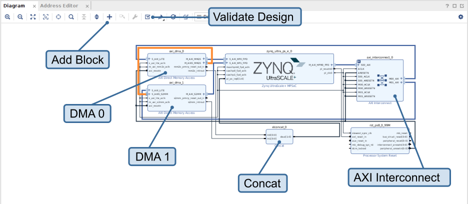
This requires us to:
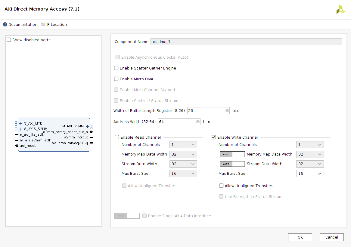
add two AXI DMAs
- configure one only with a read channel and the other one only with a write channel
- disable scatter gather
- set buffer length register and address width to max
- connect the
M_AXI_MM2Soutput of the reader DMA and theM_AXI_S2MMoutput of the writer DMA to AXI inputs of the Zynq. The example connects them directly, which requires adapting bus settings manually. In this case the DMAs use a data width of 32-bit, which also has to be configured for the inputs of the Zynq (double-click the block -> PS-PL Configuration -> PS-PL Interfaces -> Slave Interfaces, then search for the port and switch to 32-bit). Alternatively, we could add another interconnect between DMA and PS, which would adapt bus parameters automatically. - connect the
M_AXIS_MM2Soutput of the reader DMA toS_AXIS_S2MMinput of the writer DMA. This closes the loop. This is the orange connection in the figure.
add an AXI Interconnect, configure it for one input and two outputs, connect the input to a master output of the Zynq, connect the outputs to the AXI Lite inputs of the DMAs
add a Concat block with two inputs and one output that combine the interrupt outputs of the DMAs and feed it to the
pl_ps_irq0input of the Zynqrun connection automation on the remaining ports
go to the Address Editor tab and auto-assign all addresses.
This design should pass validation without errors or critical warnings.
Now, we can include our adder in the loopback path, hooking it in the orange line in the overview figure. Go to the IP Catalog, right-click, and add the HLS module from the previous step as repository. It should show that it provides one IP block, i.e., our adder. The resulting block diagram should look like this:
After that, we can check again that the design validates. I figured, it might help to add a brief video.
Finally, we generate the bitstream (use panel on the left) and export the project (File -> Export -> Export Hardware), using the fixed configuration, including the bitstream. In addition, I also export the bitstream separately in the same directory (File -> Export -> Export Bitstream File).
This already concludes the hardware part. The rest is about creating a Linux image, add and configure kernel modules, and implement user space DMA drivers.
PetaLinux
PetaLinux is toolkit to build a Linux image for Xilinx’ embedded platforms. It’s based on Yocto/OpenEmbedded, but is better integrated in the Xilinx workflow. It uses, for example, the hardware description that we just exported to pre-configure the Linux distribution.
I created a PetaLinux project
foowithpetalinux-create -t project -n foo --template zynqMP
Configure defaults with
petalinux-config --get-hw-description=../
The path in the argument points to the exported
.xsafile from Vivado. (I also had to set the machine name in theDTGmenu tozcu106-revato get Ethernet working.)We can now already build the Linux image. The first build might take quite a while, but following builds are incremental :-)
petalinux-build
I use Vivado v2020.1, which seems to have a bug the requires me to copy a file around in the PetaLinux project directory.
cp ./components/plnx_workspace/device-tree/device-tree/psu_init.tcl ./project-spec/hw-description
With this, we can boot the Linux distribution.
petalinux-boot --jtag --kernel --fpga --bitstream ../foo.bit -v
I boot using JTAG, which only requires adding some udev rules for the initial setup. Using
gtktermor a similar tool, I can connect to the board via its USB serial interface (115200, 8N1). The default login isroot:root.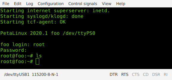
With this, me have a complete Linux system on the board. To interface the FPGA, we need DMA buffers and an AXI DMA driver.
DMA Buffers
To access DMA buffers in user space, we will use u-dma-buf, a kernel module that allocates DMA buffers and creates devices files to make them accessible in user space. For each buffer,
u-dma-bufwill create a character device/dev/udmabuf<n>, which can be mmapp’ed into user space. This allows accessing the buffer in virtual address space of the user space application.Buffers are instantiated and configured through the device tree. The device tree is mainly used for embedded devices and tells the Linux kernel about the platform/board, it’s running on (memory-mapped peripherals, clocks, interrupts, etc).
To use
u-dma-buf, we have to add it to PetaLinux and integrate it into the build. PetaLinux provides a template to add kernel modules.petalinux-create -t modules --name u-dma-buf --enable
This creates the folder
./project-spec/meta-user/recipes-modules/u-dma-buf/files, which already includesu-dma-buf.c. Replacing this file, with corresponding file of the u-dma-buf repository is everything we need to do to build the module. We can check that the module is recognized and enabled.petalinux-config -c rootfs
u-dma-bufshould show up in the modules category with a star (‘*’) indicating that the module will be built into the kernel.Finally, we have to instantiate buffers through the device tree. Most of the device tree files are auto-generated. The user can add custom configurations to
./project-spec/meta-user/recipes-bsp/device-tree/files/system-user.dtsi.We want two buffers one for the transfer from the ARM to the FPGA and one for the other direction.
/include/ "system-conf.dtsi"
/ {
    udmabuf@0x00 {
        compatible = "ikwzm,u-dma-buf";
        device-name = "udmabuf0";
        minor-number = <0>;
        size = <0x4000000>;
        sync-mode = <1>;
        sync-always;
    };

    udmabuf@0x01 {
        compatible = "ikwzm,u-dma-buf";
        device-name = "udmabuf1";
        minor-number = <1>;
        size = <0x4000000>;
        sync-mode = <1>;
        sync-always;
    };
};
This creates buffers with a size of 64Mb (0x4000000), called udmabuf0/1. The sync-related settings disable CPU caching of the buffers. This is required, since we use a non-coherent interface from the DMA controller to the main memory. If the ARM CPU had parts of the buffer in its CPU cache, it wouldn’t get notified when the DMA controller writes to the buffer. Therefore, it has no chance to invalidate the cache and use outdated values. There are several ways to deal with this issue. The MPSoC+ would even provide coherent interfaces that we could have used. But tuning this is not really relevant for the example.
Rebuilding PetaLinux (
petalinux-build) and booting the system again (petalinux-boot ..., see above) should show a boot log, indicating that the buffers were instantiated.[ 5.960619] u_dma_buf: loading out-of-tree module taints kernel. [ 5.987313] u-dma-buf udmabuf0: driver version = 3.2.4 [ 5.992494] u-dma-buf udmabuf0: major number = 243 [ 5.997468] u-dma-buf udmabuf0: minor number = 0 [ 6.002270] u-dma-buf udmabuf0: phys address = 0x0000000068500000 [ 6.008548] u-dma-buf udmabuf0: buffer size = 67108864 [ 6.013974] u-dma-buf udmabuf@0x00: driver installed. [ 6.057153] u-dma-buf udmabuf1: driver version = 3.2.4 [ 6.062317] u-dma-buf udmabuf1: major number = 243 [ 6.067283] u-dma-buf udmabuf1: minor number = 1 [ 6.072075] u-dma-buf udmabuf1: phys address = 0x000000006c500000 [ 6.078345] u-dma-buf udmabuf1: buffer size = 67108864 [ 6.083750] u-dma-buf udmabuf@0x01: driver installed.
There should be character devices in
/dev/.root@foo:/dev# ls udma* udmabuf0 udmabuf1
And sysfs entries for the metadata, in particular, the size and physical address of the buffer.
root@foo:/sys/class/u-dma-buf/udmabuf0# ls
debug_vma        driver_version   subsystem        sync_mode        uevent
dev              phys_addr        sync_direction   sync_offset
device           power            sync_for_cpu     sync_owner
dma_coherent     size             sync_for_device  sync_size
root@foo:/sys/class/u-dma-buf/udmabuf0# cat phys_addr
0x0000000068500000
Later, we’ll need the physical address to tell the DMA controller about the buffer.
User-Space DMA Driver
Now, we create a user space driver that maps the buffer in virtual memory. I started a separate project. You can find the code on GitHub.
pub struct DmaBuffer {
    name: String,
    size: usize,
    phys_addr: usize,
    buffer: *mut libc::c_void,
}
The driver does two things: it parses the sysfs files to get the metadata (size, physical address, etc) and
mmaps the character device in the virtual address space.impl DmaBuffer { pub fn new(name: &str) -> Result<DmaBuffer> { let phy_f = format!("/sys/class/u-dma-buf/{}/phys_addr", name); let mut phy_f = File::open(phy_f)?; let mut buff = String::new(); phy_f.read_to_string(&mut buff)?; let buff = buff.trim().trim_start_matches("0x"); let phys_addr = usize::from_str_radix(buff, 16)?; [...] let dev = format!("/dev/{}", name); let dev = OpenOptions::new().read(true).write(true).open(dev)?; let buffer; unsafe { buffer = libc::mmap(0 as *mut libc::c_void, size, libc::PROT_READ|libc::PROT_WRITE, libc::MAP_SHARED, dev.as_raw_fd(), 0); if buffer == libc::MAP_FAILED { anyhow::bail!("mapping dma buffer into virtual memory failed"); } } Ok(DmaBuffer { name: name.to_string(), size, phys_addr, buffer, sync_mode, debug_vma, }) } }
There is, furthermore, a helper method to cast the buffer into a typed slice. And a destructor that unmaps the buffer.
pub fn slice<T>(&self) -> &mut [T] {
    unsafe {
        slice::from_raw_parts_mut(self.buffer as *mut T, self.size / mem::size_of::<T>())
    }
}

impl Drop for DmaBuffer {
    fn drop(&mut self) {
        unsafe {
            libc::munmap(self.buffer, self.size);
        }
    }
}
Using this class, we can create a small example application that writes some integers in the buffer.
use anyhow::Result;
use xilinx_dma::DmaBuffer;

fn main() -> Result<()> {

    let buff = DmaBuffer::new("udmabuf0")?;
    println!("{:?}", buff);

    let data = buff.slice::<u32>();

    for i in 0..8 {
        data[i] = i as u32;
    }

    Ok(())
}
To test it, we need to cross-compile the binary and copy it to the board. The setup for cross-compilation depends on the OS and the distribution. There is Rust
cross, which downloads a Docker container with everything that’s needed for cross compilation. But for this simple case, it seems like overkill. I only installed a cross-compiler for aarch64 and useedrustupto add the aarch64/Linux target.sudo apt install gcc-aarch64-linux-gnu rustup target add aarch64-unknown-linux-gnu
For whatever reason, I also had to set the linker in
~/.cargo/config.toml:[target.aarch64-unknown-linux-gnu] linker = "aarch64-linux-gnu-gcc"
With this, I was able to cross-compile the example.
cargo build --example=write_dma --target=aarch64-unknown-linux-gnu
I assigned a fixed IP to the board on my router and added an SSH configuration, to ease logging in the box.
Host zcu106
    HostName 192.168.178.48
    User root
    StrictHostKeyChecking=no
    CheckHostIP no
    UserKnownHostsFile /dev/null
Usually, I also copy my public key to avoid having to enter the password every time (
ssh-copy-id zcu16). With SSH access, I can copy the binary to the board.scp target/aarch64-unknown-linux-gnu/debug/examples/write_dma zcu106:
And run it.
root@foo:~# ./write_dma
DmaBuffer (udmabuf0)
  size: 0x4000000
  phys_addr: 0x68500000
  buffer: 0x7f8aa9f000
root@foo:~# devmem  0x68500000 32
0x00000000
root@foo:~# devmem  0x68500004 32
0x00000001
root@foo:~# devmem  0x68500008 32
0x00000002
We can see that the size of the buffer matches the configuration in the device tree (0x4000000). Furthermore, the physical memory at 0x68500000 was mapped in the virtual address space of the process (at 0x7f8aa9f000). Using the
devmemutility, we read from a physical addresses and make sure that we wrote at the correct location. We see the 32-bit integers 0, 1, 2, … great. (Note that, in theory, we could just run everything as root and directly read and write to physical memory, but that’s obviously not how we want to design a system.)So with this, we have DMA-able buffers that can be memory-mapped in user space. And since we know its physical address, we can point the DMA controller to the correct location.
AXI DMA Controller
With the buffers at hand, we have to befriend the DMA controller to use the FPGA. We’ll use Linux uio (user space IO), which provides the means to create bare-minimum kernel modules and implement the main driver in user space. It provides three main functionalities. Similar to the DMA buffer, it creates a character device that can be
mmap‘ed to memory, allowing us to access associated memory regions. For drivers, this is usually memory-mapped IO, i.e., registers that are used to interface the peripheral or IP block.The exported Vivado project comes with metadata that specifies where the DMA controllers are mapped. After building PetaLinux, this information is reflected in the device tree
./components/plnx_workspace/device-tree/device-tree/pl.dtsiamba_pl: amba_pl@0 { [...] axi_dma_0: dma@a0000000 { [...] compatible = "xlnx,axi-dma-7.1", "xlnx,axi-dma-1.00.a"; interrupt-names = "mm2s_introut"; interrupt-parent = <&gic>; interrupts = <0 90 4>; dma-channel@a0000000 { [...] interrupts = <0 89 4>; }; }; axi_dma_1: dma@a0010000 { [...] dma-channel@a0010030 { [...] }; }; };We can see the two DMA controllers, mapped at 0xa0000000 and 0xa0010000.
The second part of uio drivers are interrupts, which are signaled through the character device. Writing to the device file enables the interrupt; reading from the device file blocks until the interrupt is raised.
Finally, there are sysfs entries with metadata (like the size of the memory mapped region).
The uio-part of our DMA driver is so boring, we don’t have to implement anything in the kernel. A simple default driver
uio_pdrv_genirqwill do. This driver is also the reason, why we used two DMA controllers. Multiple interrupts per device are not supported, which means we had to write a small kernel module.Using
uio_pdrv_genirqrequires giving it an id through the kernel command line (aka. bootargs) and setting thecompatibleoption of the DMA to associate it with the driver. Both is done in the device tree file, which we already used to add the DMA buffers (./project-spec/meta-user/recipes-bsp/device-tree/files/system-user.dtsi)./include/ "system-conf.dtsi" / { chosen { bootargs = " earlycon console=ttyPS0,115200 clk_ignore_unused uio_pdrv_genirq.of_id=generic-uio root=/dev/ram0 rw"; }; [...] }; &axi_dma_0{ compatible = "generic-uio"; }; &axi_dma_1{ compatible = "generic-uio"; };Rebuilding PetaLinux and booting the image, should show uio devices, two of which correspond to our DMA controllers.
root@foo:/dev# ls uio*
uio0  uio1  uio2  uio3  uio4  uio5
root@foo:/sys/class/uio# ls
uio0  uio1  uio2  uio3  uio4  uio5
root@foo:/sys/class/uio# cat uio*/name
axi-pmon axi-pmon axi-pmon axi-pmon dma dma
So uio4/5 are our DMA controllers. The
maps(in this case there is only one per device) provide more information on the memory associated with the device.root@foo:/sys/class/uio/uio4/maps/map0# ls addr name offset size root@foo:/sys/class/uio/uio4/maps/map0# cat * 0x00000000a0000000 dma@a0000000 0x0 0x0000000000010000
User Space DMA Driver
The general structure of the driver is similar to the driver of the DMA buffer. You can also find the complete version on GitHub. We open the character device associated with the driver and
mmapit. The size of the mapping is extracted from the metadata in sysfs.pub struct AxiDma { dev: String, dev_fd: File, base: *mut u32, size: usize, } pub fn new(uio: &str) -> Result<AxiDma> { let dev_fd = OpenOptions::new().read(true).write(true).open(format!("/dev/{}", uio))?; let mut size_f = File::open(format!("/sys/class/uio/{}/maps/map0/size", uio))?; let mut buf = String::new(); size_f.read_to_string(&mut buf)?; let buf = buf.trim().trim_start_matches("0x"); let size = usize::from_str_radix(buf, 16)?; let dev; unsafe { dev = libc::mmap(0 as *mut libc::c_void, size, libc::PROT_READ|libc::PROT_WRITE, libc::MAP_SHARED, dev_fd.as_raw_fd(), 0); if dev == libc::MAP_FAILED { anyhow::bail!("mapping dma buffer into virtual memory failed"); } } Ok(AxiDma { dev: uio.to_string(), dev_fd, base: dev as *mut u32, size, }) } impl Drop for AxiDma { fn drop(&mut self) { unsafe { libc::munmap(self.base as *mut libc::c_void, self.size); } } }
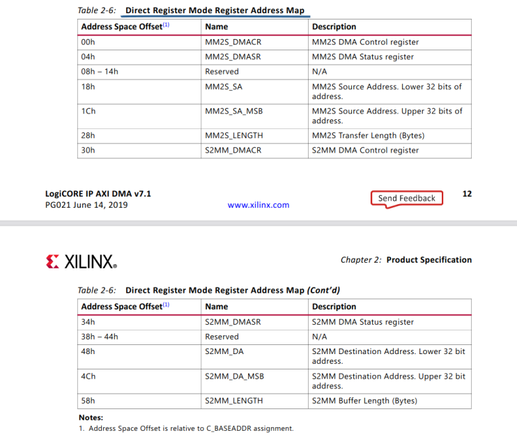
Now, we need the datasheet to figure out how the DMA controller works.
It supports two modes, register mode and scatter gather. With the latter you can set up multiple DMA transfers that will then executed in one go. This requires a more complex configuration before launching the transfer. We, therefore, use the simpler register mode in this example.
I use
ptr::read/write_volatieto force an actual read/write and avoid that stuff is reordered or optimized out. Note that the registers in the mapped memory are in the address space of the AXI Lite bus that feeds into the DMA controller.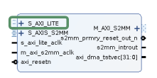
To launch a register mode transfer, we
- clear possible pending interrupts by writing to the corresponding register.
- write to the file descriptor of the device, which re-enables the interrupt in the kernel
- enable interrupts in the DMA controller
- write physical address and length of the buffer
Writing to the length register also starts the transfer.
const MM2S_DMACR:  isize = 0x0  / 4;
const MM2S_DMASR:  isize = 0x4  / 4;
const MM2S_SA:     isize = 0x18 / 4;
const MM2S_SA_MSB: isize = 0x1C / 4;
const MM2S_LENGTH: isize = 0x28 / 4;
const S2MM_DMACR:  isize = 0x30 / 4;
const S2MM_DMASR:  isize = 0x34 / 4;
const S2MM_DA:     isize = 0x48 / 4;
const S2MM_DA_MSB: isize = 0x4C / 4;
const S2MM_LENGTH: isize = 0x58 / 4;

pub fn start_h2d(&mut self, buff: &DmaBuffer, bytes: usize) -> Result<()> {
    debug_assert!(buff.size() >= bytes);
    unsafe {
        // clear irqs in dma
        ptr::write_volatile(self.base.offset(MM2S_DMASR), 0x7000);

        // enable irqs for uio driver
        self.dev_fd.write(&[1u8, 0, 0, 0])?;

        // Configure AXIDMA - MM2S (PS -> PL)
        ptr::write_volatile(self.base.offset(MM2S_DMACR), 0x7001);
        ptr::write_volatile(self.base.offset(MM2S_SA), (buff.phys_addr() & 0xffff_ffff) as u32);
        ptr::write_volatile(self.base.offset(MM2S_SA_MSB), (buff.phys_addr() >> 32) as u32);
        ptr::write_volatile(self.base.offset(MM2S_LENGTH), bytes as u32);
    }
    Ok(())
}

pub fn start_d2h(&mut self, buff: &DmaBuffer, bytes: usize) -> Result<()> {
    debug_assert!(buff.size() >= bytes);
    unsafe {
        // clear irqs in dma
        ptr::write_volatile(self.base.offset(S2MM_DMASR), 0x7000);

        // enable irqs for uio driver
        self.dev_fd.write(&[1u8, 0, 0, 0])?;

        // Configure AXIDMA - S2MM (PL -> PS)
        ptr::write_volatile(self.base.offset(S2MM_DMACR), 0x7001);
        ptr::write_volatile(self.base.offset(S2MM_DA), (buff.phys_addr() & 0xffff_ffff) as u32);
        ptr::write_volatile(self.base.offset(S2MM_DA_MSB), (buff.phys_addr() >> 32) as u32);
        ptr::write_volatile(self.base.offset(S2MM_LENGTH), bytes as u32);
    }
    Ok(())
}
Now, the question is how we know when it’s done. There are many ways. We could just busy-wait until the controller indicates that its done. We could also go and do something else and come back after some time to check the register. Or we can use the interrupt. There are two ways to do that. One option is to do a blocking read on the file descriptor of the character device. This will put the tread to sleep and allow the operating system to do something else. Once the interrupt is raised and the OS has some CPU time to spare, the thread will continue.
pub fn wait_d2h(&mut self) -> Result<()> {
    let mut buf = [0u8; 4];
    self.dev_fd.read(&mut buf)?;
    Ok(())
}

pub fn wait_h2d(&mut self) -> Result<()> {
    let mut buf = [0u8; 4];
    self.dev_fd.read(&mut buf)?;
    Ok(())
}
Note that the read needs to be 4 bytes long. It returns a 32-bit integer, counting the number of interrupts received so far.
Since FutureSDR is a runtime build around async tasks, I also tested if the file descriptor is pollable. As it turns out, this works and can be implemented with minimal effort. I only need to wrap the file descriptor in an
Asyncstruct, provided by the async runtime. It configures non-blocking mode and implements the required traits to do async writes and reads.Ok(AxiDmaAsync { dev: uio.to_string(), dev_fd: Async::new(dev_fd)?, base: dev as *mut u32, size, }) pub async fn wait_d2h(&mut self) -> Result<()> { let mut buf = [0u8; 4]; self.dev_fd.read_with_mut(|s| s.read(&mut buf)).await?; Ok(()) } pub async fn wait_h2d(&mut self) -> Result<()> { let mut buf = [0u8; 4]; self.dev_fd.read_with_mut(|s| s.read(&mut buf)).await?; Ok(()) }
I also made an example with io_uring, the beloved new mechanism for async syscalls on Linux. This is also no problem. And while the async operation might not make sense in many cases, I think it shows that we can nicely integrate any transfer mode in FutureSDR. (In the end, there is an overhead involved in setting up an async call. But so is in doing a context switch of a thread that does a blocking call. We’ll have to see how that plays out in the long run.)
AXI DMA Example
We’ll only look at the async example, since the blocking one is even easier.
fn main() -> Result<()> {

    let dma_buffer_h2d = DmaBuffer::new("udmabuf0")?;
    let dma_buffer_d2h = DmaBuffer::new("udmabuf1")?;
    println!("{:?}", dma_buffer_h2d);
    println!("{:?}", dma_buffer_d2h);

    // do not use the whole buffer
    let max_items = 1024 * 32;
    let items = std::cmp::min(max_items, dma_buffer_h2d.size()/4);
    let items = std::cmp::min(items, dma_buffer_d2h.size()/4);

    let slice_h2d = &mut dma_buffer_h2d.slice::<u32>()[0..items];
    let slice_d2h = &mut dma_buffer_d2h.slice::<u32>()[0..items];

    for i in slice_d2h.iter_mut() {
        *i = 0;
    }

    for i in slice_h2d.iter_mut() {
        *i = fastrand::u32(0..1024);
    }

    let mut dma_h2d = AxiDmaAsync::new("uio4")?;
    let mut dma_d2h = AxiDmaAsync::new("uio5")?;
    println!("{:?}", dma_h2d);
    println!("{:?}", dma_d2h);

    async_io::block_on(async {
        dma_h2d.start_h2d(&dma_buffer_h2d, items*4).await?;
        dma_d2h.start_d2h(&dma_buffer_d2h, items*4).await?;
        println!("transfers started");

        dma_h2d.wait_h2d().await?;
        println!("h2d done");
        dma_d2h.wait_d2h().await?;
        println!("d2h done");
        Result::<()>::Ok(())
    })?;

    for i in 0..items {
        assert_eq!(slice_d2h[i], slice_h2d[i] + 123);
    }

    Ok(())
}
And the corresponding output:
root@foo:~# ./async
DmaBuffer (udmabuf0)
  size: 0x4000000
  phys_addr: 0x68500000
  buffer: 0x7fa2a85000
  sync_mode: true
  debug_vma: false
DmaBuffer (udmabuf1)
  size: 0x4000000
  phys_addr: 0x6c500000
  buffer: 0x7f9ea85000
  sync_mode: true
  debug_vma: false
AxiDmaAsync (uio4)
  file: Async { source: Source { raw: 3, key: 0, state: Mutex { data: [Direction { tick: 0, ticks: None, waker: None, wakers: Arena { ... } }, Direction { tick: 0, ticks: None, waker: None, wakers: Arena { ... } }] } }, io: Some(File { fd: 3, path: "/dev/uio4", read: true, write: true }) }
  base: 0x7f9ea75000
  size: 0x10000
AxiDmaAsync (uio5)
  file: Async { source: Source { raw: 4, key: 1, state: Mutex { data: [Direction { tick: 0, ticks: None, waker: None, wakers: Arena { ... } }, Direction { tick: 0, ticks: None, waker: None, wakers: Arena { ... } }] } }, io: Some(File { fd: 4, path: "/dev/uio5", read: true, write: true }) }
  base: 0x7f9e85f000
  size: 0x10000
transfers started
h2d done
d2h done
FutureSDR Integration
Integration in FutureSDR is straightforward and very similar to the Vulkan buffers. We need to create
BufferMessagethat can be used to passDmaBuffersbetween stream port.#[derive(Debug)] pub enum BufferMessage { [...] VkBuffEmpty { buff: Arc<CpuAccessibleBuffer<[u8]>>, }, VkBuffFull { buff: Arc<CpuAccessibleBuffer<[u8]>>, used_bytes: usize, }, ZynqBuffEmpty { buff: DmaBuffer, }, ZynqBuffFull { buff: DmaBuffer, used_bytes: usize, }, }
The host part of the host-to-device (H2D) and device-to-host (D2H) buffers presents the buffer to adjacent CPU blocks like normal CPU buffers. This is all exactly the same as in the Vulkan implementation, presented in the first post.
The FutureSDR block, responsible for the FPGA integration, allocates two
DmaBuffersduring initialization. It’ll use one for H2D and one for D2H transfers. The H2D buffer is sent to the upstream block, which will fill it. The downstream buffer is kept.async fn init(&mut self, sio: &mut StreamIo) { sio.input(0).handle(BufferMessage::ZynqBuffEmpty{buff: DmaBuffer::new(&self.dma_buffs.0).unwrap()}).await; self.buff_d2h = Some(BufferMessage::ZynqBuffEmpty{buff: DmaBuffer::new(&self.dma_buffs.1).unwrap()}); }
In
work(), the block checks if it has a fullDmaBufferfrom its upstream and an emptyDmaBufferfrom its downstream and, in case, launches the DMA transfer.async fn work(&mut self, io: &mut WorkIo, sio: &mut StreamIo, _mio: &mut MessageIo<Self>, _meta: &mut BlockMeta) { for m in sio.output(0).messages().drain(..) { match m { BufferMessage::ZynqBuffEmpty{..} => { self.buff_d2h = Some(m); } _ => panic!("wrong output buffer type"), } } for m in sio.input(0).messages().drain(..) { match m { BufferMessage::ZynqBuffFull{..} => { self.buff_h2d = Some(m); } _ => panic!("wrong input buffer type"), } } if self.buff_h2d.is_some() && self.buff_d2h.is_some() { match (self.buff_h2d.take(), self.buff_d2h.take()) { (Some(BufferMessage::ZynqBuffFull{buff: inbuff, used_bytes}), Some(BufferMessage::ZynqBuffEmpty{buff: outbuff})) => { self.dma_h2d.start_h2d(&inbuff, used_bytes).await.unwrap(); self.dma_d2h.start_d2h(&outbuff, used_bytes).await.unwrap(); debug!("dma transfers started"); self.dma_h2d.wait_h2d().await.unwrap(); self.dma_d2h.wait_d2h().await.unwrap(); self.read += (used_bytes / 4) as u64; debug!("dma transfers completed"); sio.input(0).handle(BufferMessage::ZynqBuffEmpty{buff: inbuff}).await; sio.output(0).handle(BufferMessage::ZynqBuffFull{buff: outbuff, used_bytes}).await; } _ => panic!("wrong buffer types"), } } }
Complete Flowgraph
A complete flowgraph with real AXI DMA custom buffers then looks like this:
fn main() {
    futuresdr::runtime::init();

    let mut fg = FlowgraphBuilder::new().finish();

    let n_items = 100_000;
    let orig : Vec<u32> = repeat_with(|| fastrand::u32(0..1024)).take(n_items).collect();

    let src = Box::new(VectorSourceBuilder::<u32>::new(orig.clone()).finish());
    let cpy = Box::new(CopyBuilder::new(4).finish());
    let zynq = Box::new(ZynqBuilder::new("uio4", "uio5", ("udmabuf0", "udmabuf1")).finish());
    let snk = Box::new(VectorSinkBuilder::<u32>::new().finish());

    let src = fg.add_block(src);
    let cpy = fg.add_block(cpy);
    let zynq = fg.add_block(zynq);
    let snk = fg.add_block(snk);

    fg.connect_stream(src, "out", cpy, "in");
    fg.connect_stream_with_type(cpy, "out", zynq, "in", BufferType::ZynqH2D{max_bytes: 1<<14});
    fg.connect_stream_with_type(zynq, "out", snk, "in", BufferType::ZynqD2H);

    fg.run();

    let snk = fg.block_ref(snk).unwrap();
    let snk = snk.as_any().downcast_ref::<Block<VectorSink<u32>>>().unwrap();
    let v = snk.kernel().items();

    assert_eq!(v.len(), n_items);
    for i in 0..v.len() {
        assert_eq!(orig[i] + 123, v[i]);
    }
}
I like :-)
Generalization of the Approach
Finally, I wanted to add another note, since some people on Twitter mentioned that this simple example is only a simple example and, therefore, not interesting. First, GNU Radio didn’t manage to support this simple example in 18 years. There was one paper on custom buffers for CUDA that was, for whatever reason, not merged upstream. And there is RFNoC, which integrates with GNU Radio Companion (i.e., the GUI to setup GNU Radio flowgraphs) but doesn’t provide custom buffer support. These “lol not interesting” comments sound like the SDR community would be tired of winning, since proper FPGA integration is trivial and a solved problem. The opposite is true. Why would DARPA otherwise found the SDR 4.0 project, which is trying to do just that? Just these some hundred lines of Rust are already three steps forward (real custom buffers without double copy, extensible and not limited to one type of accelerator, support for async).
Second, this example is not about adding 123 to an integer but about interfacing the FPGA. So the actual question is, if FutureSDR allows proper integration of all kinds of FPGA applications. Maybe I miss something, but I think this approach seems pretty good and I don’t see any inherent limitations.
From my perspective, things boil down to a few mechanism that have to be supported (with the more complex ones being demonstrated in this example). One can either do a blocking wait in user space or busy-wait on memory-mapped registers. In these cases one can:
- indicate that the block blocks and should run in a separate thread (this is trivial to do and was discussed in the previous post)
- spawn a separate task (not block) that does the blocking/busy-waiting and signals through the inbox of the block (-> actor pattern) once there is new data available
These two cases are straightforward and integrate nicely.
One could also wait a given time and then recheck the register (ignoring the interrupt). This can also easily be done, since timers are not an issue. This was also discussed in the previous post (see the periodic message source example).
In addition to these simple mechanisms, one can do a non-blocking/async wait, as demonstrated in the example. And that’s every mechanism, I could come up with. As far as I see, all of them go well with this approach. And that’s the point.